Whats RF Ferrite Isolator Basics
Posted on 02 May 2024
What is an RF Ferrite Isolator?
An isolator is a type of non-reciprocal passive network that allows designers the freedom to construct networks where the transmission coefficient in one direction does not necessarily have the same loss as in the reverse direction. In an isolator, ideally, RF energy can be made to flow through it in only one direction.
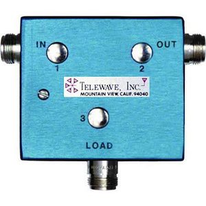
Isolators are derived from circulators, which are three-port devices. In an ideal circulator, all energy that enters port 1 is delivered to port 2, all energy that enters port 2 is delivered to port 3, and all energy that enters port 3 is delivered to port 1. To construct an isolator, port 3 is terminated in a matched load so that energy can still flow from port 1 to port 2, but energy in the reverse path (port 2 to port 1) is fully dissipated.
The main element in a circulator or isolator is magnetically biased ferro-ceramic material sandwiched between powerful magnets, often in a metallic enclosure. A thin foil of copper is laid on top of the magnet, and the magnet induces a strong magnetic field into the copper foil. The radio frequency energy thus follows the magnetic lines of flux induced on the copper foil and follows those induced fields in a one-way direction. Thus, this is how a directional coupler works. The direction of flow is determined by the strength and arrangement of the magnetic field inside the enclosure. Signal flow can be clockwise or counterclockwise, depending on the configuration of the magnet: flip the magnet upside down in a circulator, and the direction will reverse.
Without an isolator, unwanted energy that reflects back to the transmitter could potentially contribute to signal distortions or cause damage to the equipment. Unwanted signals reflected down the transmission line toward the transmitter could be caused by many factors, such as a broken antenna, shorted or open cable, age, water invasion, incorrect cable length, or strong nearby signal source. (picture of Telewave T-1530)
An isolator is a type of non-reciprocal passive network that allows designers the freedom to construct networks where the transmission coefficient in one direction does not necessarily have the same loss as in the reverse direction. In an isolator, ideally, RF energy can be made to flow through it in only one direction.
Isolators are derived from circulators, which are three-port devices. In an ideal circulator, all energy that enters port 1 is delivered to port 2, all energy that enters port 2 is delivered to port 3, and all energy that enters port 3 is delivered to port 1. To construct an isolator, port 3 is terminated in a matched load so that energy can still flow from port 1 to port 2, but the energy in the reverse path (port 2 to port 1) is fully dissipated.
The main element in a circulator or isolator is magnetically biased ferro-ceramic material sandwiched between powerful magnets, often in a metallic enclosure. A thin foil of copper is laid on top of the magnet, and the magnet induces a strong magnetic field into the copper foil. The radio frequency energy thus follows the magnetic lines of flux induced on the copper foil and follows those induced fields in a one-way direction. Thus, this is how a directional coupler works. The direction of flow is determined by the strength and arrangement of the magnetic field inside the enclosure. Signal flow can be clockwise or counterclockwise, dependent on the configuration of the magnet: flip the magnet upside down in a circulator, and the direction will reverse.
Without an isolator, unwanted energy that reflects back to the transmitter could potentially contribute to signal distortions or cause damage to the equipment. Unwanted signals reflected down the transmission line toward the transmitter could be caused by many factors, such as a broken antenna, shorted or open cable, age, water invasion, incorrect cable length, or strong nearby signal source. (picture of Telewave T-1530)
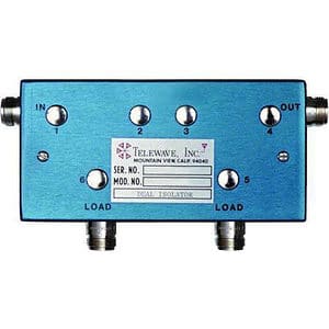
For effective isolation, the isolator port that is to be terminated must be well-matched. Indeed, the isolation of an isolator is only as good as its port match. In practice, it is difficult to achieve return losses of more than 20 dB in an isolator over moderate bandwidths. In some applications, 20 dB isolation isn’t enough. Two isolators in the transmission line would double isolation, but it’s often more efficient and cost-effective to use a dual-stage isolator to improve matching between stages. A dual-stage isolator, like the single isolator, only allows the signal to pass in one direction but there are six ports in the network instead of three, and only four external ports. Following the labelled external and internal ports in the dual circulator below, the signal still comes in port 1, then out port 2, but port 2 of the left-side isolator is now connected to port 3 (the input of the right-side isolator). Port¬ 3 passes the signal to port 4, and out the connection on port 4 to deliver power where it is needed (an antenna for example).
Any signal that enters the device through port 4 gets routed to port 5, terminated by the first load. This first load should be sized to handle the full signal that might be reflected, as it will be dissipating 99% of the unwanted power. Power that reflects off of port 5 is routed to port 6, where a second load further dissipates the already-weak signal (picture of Telewave T-1560). Note that it is often a good idea to size the high-power load to handle the full transmit power, in case the user accidentally leaves the output port open-circuited.
There is an energy cost to all isolators that is minimized by best practices. Insertion loss is a measurement of the amount of energy lost, in dB, when the signal passes through the isolator. The lower the insertion loss, the more of the desired signal makes it through the device.
Isolators have limited bandwidth, usually less than an octave. Like many other microwave networks, more bandwidth is traded for lower performance. Each isolator is manufactured for a specific range and tuned to a specific frequency. Some isolators can be fine-tuned in the field by turning the capacitors at each port (including the internal ones for dual-stage isolators). For more information about tuning isolators, see Telewave’s “Single and Dual Isolator Field Tuning Guide” available for download at
Source: https://www.telewave.com/products/rf-isolators/